
PIC Handling Tweezers: Contact Zone and Tip Geometry Checklist
A tweezer should not be described as suitable for photonic integrated circuit or component handling only because it has fine tips. Approval begins with the component drawing, permitted contact zone and damage risks. The tool geometry must then be measured and tested against representative parts under the buyer’s controlled procedure.
1. Mark the permitted contact zone
Identify where mechanical contact is allowed: package edge, handling tab, carrier, robust substrate area or another defined feature. Mark prohibited areas such as optical faces, wire bonds, active regions, delicate coatings and exposed structures. If the permitted zone is not defined, tool selection is premature.
2. Describe the component
- overall length, width and thickness;
- mass and center-of-gravity concerns;
- edge radius and accessible clearance;
- surface or coating sensitivity;
- orientation during pickup and placement;
- representative reject, dummy or qualification samples.
3. Measure the tweezer tip
Record tip width and thickness at agreed distances from the end, point radius, inside-face geometry, opening range, arm length and working angle. A nominally fine tip may still be too thick for the available clearance or too sharp for an approved edge-contact area.
4. Review contact-face geometry
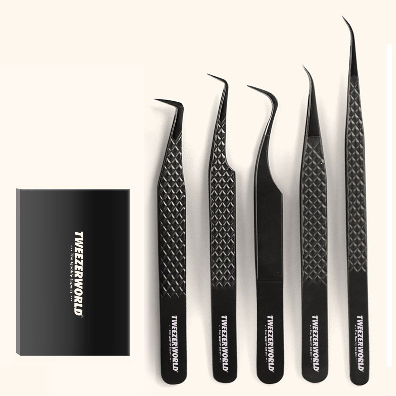
Compare pointed, flat, paddle, radiused, grooved, ceramic, polymer or replaceable-tip candidates only where those options are actually available and documented. Surface appearance alone does not prove non-marring behavior, particle performance, electrical characteristics or chemical compatibility.
5. Control closing action and force
Observe alignment through the closing range and measure force using an agreed method when force matters. Reverse-action tools require separate evaluation because their default holding condition differs from standard-action tweezers. The goal is stable handling without exceeding the component’s approved mechanical limits.
6. Define environmental evidence
If ESD control, magnetism, cleanliness, outgassing, chemical resistance or cleanroom use matters, state the required test method, acceptance limits and responsible laboratory. Do not infer these attributes from stainless steel, ceramic tips, color or a catalog label.
7. Run a controlled sample plan
Use coded tools and representative components. Record pickup, orientation, transfer, placement, release, visible marking, edge damage, particles, slippage and operator comments. Include a defined number of cycles and inspection method. Retain the approved golden sample and drawing revision.
PIC qualification checklist
- Component drawing and revision
- Permitted and prohibited contact zones
- Tip width, thickness, radius and profile
- Opening and access clearance
- Alignment and closing-force method
- Surface and substrate evidence
- Electrical and environmental requirements
- Representative sample plan
- Acceptance criteria and inspection record
- Production batch-control requirement
Related collections and buyer support
- semiconductor micro-handling tweezers
- precision tweezers
- electronics repair tweezers
- anti-static tweezer candidates
- pointed tweezers
- watchmaker precision tweezers
- industrial tweezer sets
- photonics precision tweezers
- OEM development process
- submit a technical RFQ
Request a controlled-contact evaluation set
Send the component drawing, permitted contact zone, representative sample plan and required measurements. Name the exact candidate SKU where available; PIC compatibility, ESD status, material and environmental claims remain pending until model-specific evidence is reviewed.
Contact TWEEZER WORLD® or review the OEM process before submitting the request.
Papular Products Gallery