
Optical Sensor & Infrared Component Tweezers Guide
Tweezers for Optical Sensors and Infrared Components
Optical sensors and infrared components are used in proximity detection, machine vision, access control, industrial automation, medical equipment, telecommunications, environmental monitoring, consumer electronics and many other systems. Although these parts are often small, they are not interchangeable from a handling perspective. A moulded surface-mount ambient-light sensor, a metal-can photodiode, an infrared emitter, an optical filter and a bare detector die can require very different tools and controls.
The most suitable tweezer is therefore selected by the permitted contact area, component packaging, electrostatic-discharge risk, contamination sensitivity, access angle and required handling force. Material names such as “stainless steel,” “titanium,” “ceramic” or “non-marring” are useful starting points, but none of them proves that a tool is suitable for every optical or infrared application.
This guide explains how electronics manufacturers, optical laboratories, service teams, distributors and OEM buyers can specify tweezers for optical sensors and infrared components without relying on vague claims.
Handling notice: Always follow the component manufacturer’s datasheet, handling precautions, ESD controls, clean-environment requirements and safety instructions. Unless the approved procedure states otherwise, use tweezers only on the permitted package body, flange, edge or other defined handling zone—not on an active detector area, optical window, lens, filter coating or exposed die. This article is a tool-selection and procurement guide, not a component-specific work instruction.
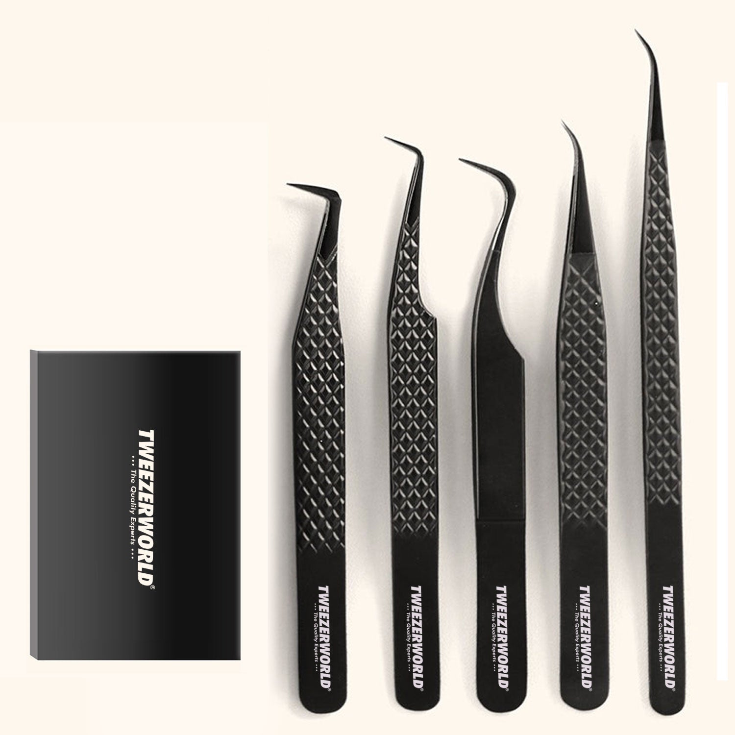
Explore TWEEZER WORLD®’s ESD and Anti-Static Tweezers, ESD Stainless-Steel Tweezers and Ceramic Tweezers.
Why Optical and Infrared Components Need Controlled Handling
An ordinary mechanical part is often judged mainly by whether it can be gripped securely. Optical and infrared components introduce additional risks. A part may remain electrically functional while contamination, a scratch, a bent lead or damage to a coating changes the way light enters, leaves or passes through the assembly.
Electrostatic Discharge
Photodiodes, image sensors, proximity sensors, optical receivers, emitters and their supporting integrated circuits may be electrostatic-discharge sensitive. Tool selection must therefore form part of the buyer’s complete ESD-control programme. The current IEC 61340-5-1:2024 sets requirements for an ESD-control programme, while IEC TS 61340-5-4:2026 addresses compliance-verification testing for technical items included in such a programme.
A tweezer’s name or colour is not sufficient evidence. Buyers should define which electrical characteristic applies, how it will be measured and how the tool will be used with grounded personnel, work surfaces, packaging and other controls.
Contamination and Optical Performance
Fingerprints, dust, oil, polishing residue, adhesive and transferred particles can obstruct an optical path or change surface behaviour. Hamamatsu’s handling information for one InGaAs PIN photodiode, for example, instructs users to handle the device with tweezers and gloves, avoid bare-hand contact and keep sharp or hard objects away from its soft resin area. That instruction is product-specific, but it illustrates why a generic “use precision tweezers” statement is incomplete.
The approved tool must be clean at the moment of use. Even a soft tip can mark a component if it contains embedded metal or abrasive particles.
Scratches and Coating Damage
Optical windows, filters and lenses may have functional coatings. A scratch that looks minor under ordinary room lighting may be unacceptable for the component’s intended wavelength or image quality. Metal tips should not touch coated optical areas unless the component manufacturer and validated process explicitly permit that contact.
Mechanical Fragility
Thin leads, small solder terminations, flex circuits, soft encapsulants, glass windows and bonded interfaces can be damaged by concentrated force. Very fine points increase access but also concentrate pressure. Reverse-action tools reduce hand fatigue but may apply a continuous holding force that is excessive for a fragile package.
Restricted Access and Visibility
Sensors are frequently installed behind shields, in recessed housings or close to connectors and other components. A curved or angled tool can improve visibility and approach angle, but only if the tip profile, alignment and strength are appropriate for the task.
Begin With the Permitted Handling Zone
The component’s approved handling zone should be identified before the tweezer pattern is chosen. If the drawing, datasheet or work instruction does not show where the part may be gripped, obtain clarification from the component manufacturer or responsible process engineer.
| Component area | Typical concern | Procurement approach |
|---|---|---|
| Package body or metal flange | Crushing, slipping, cosmetic marking or contamination | Often the preferred gripping zone when the component documentation permits it; define tip width, surface, force and contact location. |
| Leads or terminals | Bending, plating damage, contamination and altered coplanarity | Avoid using leads as the primary grip unless the approved process specifically allows it. |
| Optical window, lens or coated filter surface | Scratches, fingerprints, coating damage and obstructed optical path | Do not contact with ordinary tweezer tips. Use an approved edge-handling, vacuum or dedicated optical-handling process. |
| Filter, lens or window edge | Edge chips, excessive local pressure and tip slip | Use a clean, broad or non-marring geometry only where edge handling is permitted and tested. |
| Bare die or detector surface | Catastrophic surface, bond-pad or structural damage | Use specialist die-handling tooling and a validated process; generic hand tweezers may be unsuitable. |
| Flex cable, connector or module frame | Tearing, creasing, latch damage and residue | Select a rounded, smooth or task-specific non-marring tip and define the approved contact zone. |
Tool Selection by Optical or Infrared Task
| Handling task | Useful starting configuration | Important qualification checks |
|---|---|---|
| Placing a packaged ambient-light, colour, proximity, time-of-flight or infrared receiver sensor | Fine straight ESD-programme-compatible tweezer | Permitted package contact zone, electrical evidence, alignment, closing force, burr-free faces and compatibility with the pick-and-place or rework process |
| Handling a metal-can photodiode, phototransistor or infrared emitter | Fine curved or smooth rounded tip sized for the package body | Grip the approved body or flange rather than the window or leads; evaluate slip and local pressure |
| Reaching a recessed sensor module | Fine curved or angled tweezer | Access path, sight line, curve symmetry, adjacent-part clearance and tip strength |
| Handling an approved edge of an optical filter, window or lens | Clean, broad, flat or non-marring edge-handling tip | Edge pressure, coating clearance, cleanliness, particle transfer and proof using representative parts |
| Holding a packaged component during a controlled hot process | Ceramic-tip or other temperature-qualified configuration | Declared temperature, exposure time, thermal cycling, brittleness, tip security and ESD-process compatibility |
| Temporary hands-free holding | Reverse-action tool with defined contact geometry | Holding force, release control, jaw contact and risk of deformation or launching the part |
| Handling a bare detector die or highly fragile unencapsulated optical element | Specialist vacuum, collet, soft-tip or die-handling equipment selected by the process engineer | Do not substitute a generic tweezer without component-specific validation |
These are starting configurations, not universal approvals. Sample tools should be evaluated with representative components, the actual workstation and the planned cleaning and handling procedure.
Best Tweezer Shapes for Optical-Sensor Work
Fine Straight Tips
Fine straight tips provide a direct sight line and are commonly considered for small packaged sensors and electronic parts. Specify the closed-tip width, thickness, point radius and intended contact area. An ultra-fine point should not be used simply because the component is small; excessive sharpness can increase marking risk and reduce resistance to bending.
Fine Curved Tips
Curved tips can reach around a package, shield or housing while keeping the operator’s hand outside the direct line of sight. The curve should be symmetrical, and the tips should meet at the specified working area under a defined closing force. Curved tweezers are especially useful when the component must be approached from above and the side.
Rounded or Blunt Tips
Rounded tips distribute contact over a larger area than a needle point and can reduce the risk of puncturing soft packaging or flex material. They can be useful for larger optical modules and permitted package surfaces. “Rounded” does not mean “non-marring”: edge finish, cleanliness and applied force still matter.
Flat, Paddle or Spade Tips
Broader flat tips can support a thin filter, window or mechanical frame over a larger area. They must not overlap the active optical region or contact a functional coating. Specify flatness, corner radius, parallel contact, thickness and the exact part edge that the tool may touch.
Reverse-Action Tips
Reverse-action tweezers close when hand pressure is released. They can provide consistent temporary holding during inspection or assembly, but the holding force must be qualified. A spring force that is acceptable for a metal package can damage a thin glass edge, soft encapsulant or small leaded sensor.
Replaceable Tips
Replaceable-tip models make it possible to renew worn contact surfaces or select different materials for separate workstations. The replacement process must preserve alignment and cleanliness. Buyers should control tip part numbers, fastener security, permitted tightening method, spare availability and post-replacement inspection.
Stainless Steel vs Titanium vs Ceramic and Non-Marring Tips
| Material family | Potential advantages | Procurement cautions |
|---|---|---|
| Stainless steel | Durable, electrically conductive, available in many shapes and capable of fine working ends | The description does not identify alloy, hardness, magnetic response, passivation, surface finish or ESD qualification. Hard sharp points may damage soft or coated areas. |
| Low-magnetic-response stainless or specialty alloy | Useful near magnetically sensitive devices or assemblies where magnetic attraction must be limited | “Non-magnetic” and “anti-magnetic” need a defined test method and acceptance limit. Response varies by alloy, processing and geometry. |
| Titanium alloy | Low weight, corrosion resistance and generally low magnetic response | Titanium is electrically conductive and is not automatically suitable for an ESD process. Exact alloy, stiffness, wear and surface finish must be considered. |
| Ceramic tip | Electrically insulating contact area, low magnetic interaction and useful temperature resistance in selected processes | Ceramic may chip under impact or side load. Insulation is not the same as ESD compatibility. Request temperature and mechanical evidence for the exact tip and attachment. |
| Polymer or engineered-plastic tip | Can reduce direct metal contact and lower marking risk on selected package or optical-element edges | Wear, solvent compatibility, temperature capability, particle shedding and electrical properties vary. Contaminated soft tips can still scratch. |
| Carbon-fibre or composite tip | May combine low weight, specific electrical behaviour and non-metal contact | Composition and performance vary widely. Require model-specific electrical, mechanical, cleanliness and chemical-compatibility data. |
The best material is the one that meets the documented process requirements. There is no universally superior tweezer material for all optical sensors, infrared detectors, filters and emitters.
ESD-Compatible Does Not Mean Electrically Insulated
This distinction is essential. A conductive stainless-steel or titanium tweezer may be appropriate in a controlled ESD process because charge can be managed through the programme. The same conductive tool is not a voltage-insulated safety tool. An insulating ceramic tip also does not automatically make the complete tool suitable for work on energised equipment.
A professional specification should state:
- The component’s ESD sensitivity and applicable control plan
- The required electrical characteristic of the complete tool or specified section
- The test method, electrodes, voltage and conditioning environment
- Acceptance limits and measurement uncertainty where relevant
- Whether results apply to qualification samples, production batches or periodic verification
- Cleaning and ageing conditions before retesting
- How replacement tips are identified and verified
Do not use standard ESD, ceramic-tip or coated tweezers as substitutes for tools specifically designed and approved for the applicable electrical hazard.
Cleanliness and Controlled-Environment Requirements
A “cleanroom tweezer” claim should not be based only on packaging appearance. ISO 14644-1:2015, which ISO currently lists as published, classifies air cleanliness by airborne-particle concentration. It does not by itself certify an individual hand tool or establish that a tweezer is suitable for every controlled process.
Where cleanliness matters, define the product-level requirements separately:
- Permitted manufacturing, cleaning and packaging environment
- Particle, fibre, oil, ionic-residue or other contamination criteria
- Approved cleaning agent and method
- Rinse-water and drying requirements, if applicable
- Compatibility with the intended solvent, disinfectant or plasma process
- Glove and handling requirements after final cleaning
- Individual packaging, double-bagging or other transfer controls
- Storage conditions and shelf-life basis for clean packaging
- Inspection frequency and release records
The end user should also separate tools by task where cross-contamination is possible. A tweezer used with adhesive, soldering flux or general mechanical hardware should not be returned to clean optical handling without an approved cleaning and verification process.
How to Inspect Tweezers Before Approval
Tip Alignment and Contact
Inspect lateral and vertical alignment from several viewing directions. Define where the tips should first contact, the allowed offset or gap and the closing force used during inspection. A phrase such as “precision aligned” is less useful than a measurable drawing requirement.
Surface and Edge Condition
Check contact faces and edges under suitable magnification for burrs, chips, pits, polishing residue, coating defects and embedded particles. For non-marring tips, inspect for wear and contamination after representative use and cleaning.
Closing Force, Return and Holding Force
Measure closing force at a specified opening and handle position. For reverse-action tools, define the holding force and release behaviour. Excessive force can damage the component; insufficient force can allow a part to slip or be launched.
Functional Handling Test
Use a representative dummy part or an approved production component. Define the pick-up location, angle, number of cycles, dwell time and acceptance criteria. Inspect the part afterwards for scratches, residue, chips, bent leads, deformation or other damage. A pass with one package size should not be presented as proof for every optical component.
Electrical and Magnetic Verification
Where these properties matter, test the exact finished model using the agreed method. A raw-material certificate does not necessarily describe the complete coated tool, replaceable-tip assembly or behaviour after cleaning.
Temperature and Chemical Compatibility
For hot processes, record temperature, exposure duration, number of cycles and post-test alignment, strength and surface condition. For cleaning processes, evaluate swelling, cracking, corrosion, residue, discolouration and changes in electrical performance.
Tip Security
For replaceable or bonded tips, inspect attachment security before and after the planned usage cycles. A loose fastener or damaged bond can change alignment and create a contamination or foreign-object risk.
Avoid Unsupported Marketing Claims
| Broad claim | Why it can mislead | Better specification or wording |
|---|---|---|
| ESD safe | Does not identify the measured property, test method, range or part of the tool | State the electrical characteristic, method, conditioning and acceptance limits for the exact model. |
| Scratch-proof | No tweezer can prevent all marking under every force, contamination level and surface condition | “Designed to reduce marking risk on the specified surface when clean and used according to the approved procedure.” |
| Cleanroom-grade | Does not define environment, cleaning, particle criteria or packaging | State the manufacturing, cleaning, packaging and product-release requirements. |
| Non-magnetic | Magnetic response depends on material, processing, geometry and test sensitivity | Define the test method and maximum permitted response. |
| Heat-proof | Temperature capability depends on exposure time, cycling and the complete tip assembly | State the tested temperature, duration, cycles and post-test acceptance criteria. |
| Optical grade | Does not identify which optical component or surface may be contacted | Define the approved component, handling zone, cleanliness and functional test. |
| Perfectly aligned | Absolute wording ignores force, viewing method and measurement limits | Specify the permitted gap or offset, contact zone, magnification and closing force. |
| IR safe | The phrase does not describe ESD, radiation, heat, contamination or component-protection performance | Describe the exact infrared-component task and each verified requirement separately. |
Optical and Infrared Tweezer Procurement Checklist
The following completed example can be adapted for an RFQ. Replace the bracketed details and model-specific values with requirements approved by the buyer’s engineering and quality teams.
| Procurement field | Buyer’s requirement |
|---|---|
| Product name | Precision tweezer for packaged optical sensors and infrared components |
| Model and task | Unique model for each defined task; no substitution between straight, curved, reverse-action and non-marring configurations |
| Approved component | List manufacturer, part family, package dimensions and approved representative test part |
| Permitted handling zone | Package body, flange or defined edge shown on the controlled work instruction; no contact with optical window, lens, coating or active area unless specifically approved |
| Tip shape | Fine straight, fine curved, rounded, flat or other geometry according to the task drawing |
| Tip dimensions | Closed width, thickness, radius, curve and tolerances defined at stated measurement points |
| Material | Exact stainless-steel, titanium, ceramic, polymer or composite grade declared; substitutions require prior written approval |
| Surface finish | Uniform, clean and burr-free contact surfaces with no pits, cracks, chips, residue or unintended sharp edges |
| Alignment | Tips meet within the drawing limit under the specified closing force without crossover, twisting or unstable contact |
| Closing or holding force | Model-specific range measured at the defined opening and handle position |
| ESD requirement | Electrical characteristic, test method, conditioning and limits agreed with the buyer’s ESD coordinator; evidence applies to the complete supplied model |
| Magnetic requirement | Test method and maximum response specified only where the application requires it |
| Temperature requirement | Maximum process temperature, exposure time, number of cycles and post-test criteria defined for hot-zone models |
| Chemical compatibility | Compatible with the approved cleaning agent and process without residue, swelling, corrosion, cracking or performance loss |
| Cleanliness | Cleaning, handling, packaging and product-release criteria defined for the actual controlled environment |
| Functional test | Repeated pick, hold, position and release test using the approved component or dummy; no slip, launch, visible marking, deformation or contamination under the stated method |
| Replaceable-tip controls | Stable spare-tip reference, attachment method, alignment check and replacement instructions required where applicable |
| Packaging | Individually protected tips, no metal-to-metal contact, clean packaging as specified and clear model or lot identification |
| Documentation | Approved drawing, material declaration, inspection report, applicable electrical and functional test evidence, cleaning instructions and batch conformity record |
| Approved sample | Signed golden sample linked to drawing, specification and work-instruction revisions |
| Change control | No unapproved change to material, tip geometry, finish, coating, supplier, manufacturing process, cleaning, packaging or inspection method |
Building a Tool Set for Optical and Infrared Work
A professional kit should contain distinct models for distinct contact conditions. Colour coding, etched identifiers or controlled tray positions can help prevent the wrong tool from being used on a sensitive component.
Optical-Sensor Assembly Set
- Fine straight ESD-programme-compatible tweezer for packaged SMD sensors
- Fine curved model for recessed locations
- Rounded-tip model for larger package bodies and module frames
- Dedicated inspection loupe or magnifier, where required by the work instruction
Infrared Component Service Set
- Fine curved tool for TO-can and leaded packages
- Medium-fine straight tool for general mechanical parts
- Ceramic-tip model for an approved hot or low-magnetic-interaction task
- Protective storage with individual model identification
Clean Optical-Handling Set
- Broad, smooth or non-marring edge-handling model
- Replacement tips and a controlled change procedure
- Dedicated clean storage and transfer packaging
- Cleaning instructions and inspection record
Do not combine used soldering, adhesive-handling and clean optical tools in one uncontrolled pouch. The tool set should support segregation, inspection and replacement as well as convenience.
Packaging, Storage and Maintenance
Fine tips can be damaged before the buyer performs the first inspection. Specify a rigid or semi-rigid tip protector that does not force the arms sideways. Individual sleeves, trays or cases should prevent tools from striking one another during transport.
For controlled environments, agree how packaging enters the work area and whether single or double bagging is required. Labels should identify the model, lot, tip material and any use restriction. Replaceable tips should remain traceable to their own part number and batch where required.
Maintenance instructions should define:
- Permitted cleaning agents and concentrations
- Manual or automated cleaning method
- Rinsing and drying
- Inspection magnification and lighting
- Alignment, chip, wear and contamination checks
- Electrical re-verification intervals where applicable
- Replaceable-tip installation and inspection
- Criteria for removal from service
Discard or quarantine a tool with a bent point, chipped ceramic, worn polymer contact, loose tip, corrosion, embedded particle or uncertain cleanliness until it has been evaluated under the approved procedure.
OEM and Private-Label Optical Component Tweezer Sets
Distributors, laboratories and electronics brands may require customised sets for optical-sensor assembly, infrared detector service, photonics training or production support. A professional OEM project should begin with the component list and work instructions, not only a requested colour or logo.
Define:
- Application and permitted component contact areas
- Tool models and tip geometries
- Material, finish and electrical requirements
- Closing-force ranges
- Cleanliness and packaging controls
- Inspection and batch documentation
- Model marking and colour coding
- Custom case, tray, label and instructions
- Spare-tip supply
- Golden samples and change control
TWEEZER WORLD® can discuss tool shapes, material options, custom sets, private-label marking and packaging for wholesale and OEM buyers. Learn more about OEM and Private-Label Tweezer Manufacturing and our manufacturing capabilities. Suitability and supporting documentation should be confirmed for the exact product, component and destination market.
Frequently Asked Questions
Which tweezers are best for optical sensors?
There is no single best model. Packaged SMD sensors may suit fine straight ESD-programme-compatible tweezers, while recessed modules may benefit from curved tips. Optical elements may require broad non-marring edge-handling tools or specialist vacuum handling. Start with the component manufacturer’s permitted handling zone.
Can tweezers touch the window of a photodiode or infrared sensor?
Do not allow ordinary tweezer tips to touch an optical window, lens, coating or active detector area unless the component manufacturer and validated work instruction expressly permit it. Grip the approved package body, flange or edge instead.
Are ceramic tweezers automatically ESD safe?
No. A ceramic tip is generally electrically insulating, but insulation and ESD suitability are not the same. The complete tool must be evaluated within the site’s ESD-control programme.
Are titanium tweezers better for infrared components?
Titanium can be useful because it is light, corrosion resistant and generally has low magnetic response. It remains conductive and is not universally better than stainless steel, ceramic or non-marring materials. Select it only when its verified properties match the task.
What does non-marring mean for an optical tweezer?
It should mean that the tip material and geometry are intended to reduce marking risk on a specified surface under defined conditions. It should not be interpreted as a guarantee against all scratches. Cleanliness, force, edge finish and part coating remain important.
Can the same tweezer handle filters, lenses and electronic sensors?
Usually it is better to separate these tasks. A fine conductive tweezer selected for packaged sensors may be too sharp for a filter edge, while a broad polymer tip may not provide the access required for an SMD package. Dedicated tools also reduce cross-contamination.
How should tip alignment be specified?
Define the intended contact zone, maximum gap or offset, viewing or measurement method, magnification and closing force. For a functional approval, add a repeatable handling test with a representative component.
What evidence should a distributor request?
Request an approved drawing, exact material declaration, model-specific inspection report, applicable electrical and functional test evidence, cleaning instructions, packaging specification, golden sample reference and change-control agreement.
Can ordinary electronics tweezers be used on energised infrared equipment?
Do not assume so. Standard stainless-steel, titanium, ESD or ceramic-tip tweezers are not automatically voltage-insulated safety tools. De-energise equipment and follow the equipment manufacturer’s instructions and applicable electrical-safety procedures.
Conclusion
Tweezers for optical sensors and infrared components should be specified around the permitted contact area and verified process. Tip shape affects access and pressure distribution; material affects conductivity, stiffness, magnetic response, heat behaviour and marking risk; cleanliness determines whether the tool protects or contaminates the optical assembly.
Before placing a bulk order, define the component, handling zone, tool geometry, force, ESD requirement, cleanliness, functional test, packaging, inspection records and change controls. This converts broad descriptions such as “ESD safe,” “cleanroom-grade” and “non-marring” into requirements that a buyer and supplier can evaluate consistently.
Papular Products Gallery