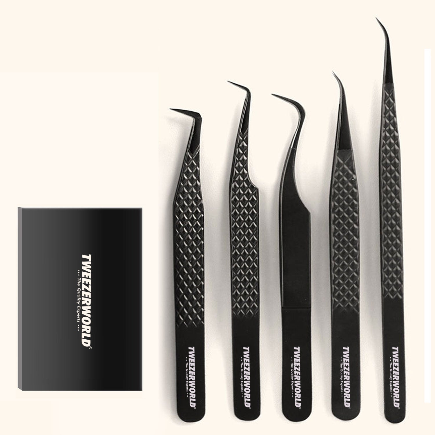

ESD Tweezer Documentation: What Buyers Should Request
How Electronics Distributors Evaluate ESD Tweezer Specifications
Electronics distributors are often offered tweezers described as “ESD safe,” “anti-static,” “conductive,” “non-magnetic” or “precision grade.” Those descriptions do not tell a buyer how the tool was tested, whether the result applies to the complete tweezer, whether production batches are consistent or whether the tool is suitable for the customer’s ESD-control program.
A credible ESD tweezer specification should connect the product’s material, construction, electrical behavior, tip geometry and mechanical performance to a defined test method and acceptance criteria. It should also explain how the manufacturer controls changes after approval.
This guide gives distributors, importers, OEM brands and technical procurement teams a structured method for reviewing supplier documents, evaluating samples and building a defensible incoming-inspection plan.
Important distinction: ESD-compatible, conductive and static-dissipative tools are not automatically electrically insulated. Many ESD tools intentionally conduct charge. They must not be represented as electric-shock protection unless the exact tool has been separately designed, tested, rated and marked for that purpose.
Why “ESD Safe” Is Not a Complete Specification
Electrostatic-discharge control is a system. It can involve an ESD-protected area, personnel grounding, work surfaces, packaging, equipment, training, product qualification and ongoing compliance verification. A tweezer is only one element.
The EOS/ESD Association describes ANSI/ESD S20.20 as a framework for establishing, implementing and maintaining an ESD-control program. The program includes administrative and technical controls rather than relying on one product label. Read the Association’s overview of ANSI/ESD S20.20.
Instead of asking only whether a tweezer is ESD safe, ask:
- What electrical property and resistance range are specified?
- Was the complete assembled tool tested?
- Which test method, electrodes, voltage and measurement points were used?
- How were samples conditioned before testing?
- How many samples and production lots were evaluated?
- Does cleaning, wear or tip replacement change the result?
- How will each incoming batch be verified?
Start With the Customer’s ESD-Control Program
A distributor should not set one universal resistance requirement for every buyer. Electronics assembly, semiconductor rework, data-centre maintenance, optical-module handling, laboratory work and education can use different control plans, work surfaces and qualification methods.
Before approving a model, identify the handled devices, applicable standard or internal control plan, use inside or outside an ESD-protected area, grounding arrangement, permitted materials, cleaning frequency, environment and required qualification records.
Server manufacturers provide a practical example of system-level control. NVIDIA’s DGX safety guidance recommends an ESD workstation or grounded wrist strap when handling sensitive parts and directs personnel to place boards on grounded, static-free surfaces. See the applicable NVIDIA server ESD guidance. A conductive tweezer alone does not replace those controls.
Evaluate the Exact Electrical Claim
| Claim | What to request | Common problem |
|---|---|---|
| Conductive | Resistance range, test method and measurement path | Only raw material is tested |
| Static dissipative | Upper and lower limits plus conditioning and test voltage | One unconditioned reading is treated as universal |
| Anti-static | A measurable electrical property and intended control function | The term is only marketing language |
| ESD safe | Compatibility rationale for the target control program | No standard, method or acceptance range |
| Insulated | Separate voltage rating, applicable tool standard, report and marking | ESD coating is mistaken for shock protection |
Do not accept a resistance value without units, limits and test context. A statement such as “resistance: 10⁶” is incomplete because it does not identify the unit, tolerance, measurement points, voltage, equipment, conditioning or sample state.
Confirm What Was Actually Measured
An ESD tweezer can contain a metal body, coating, polymer grips, replaceable tips, screws, adhesive and markings. Measuring a flat raw-material coupon is not the same as measuring the finished instrument.
The report should identify:
- Complete product model, revision and production lot
- Number of samples and measurement path
- Electrode design and contact pressure
- Instrument and calibration status
- Applied voltage, temperature, humidity and conditioning time
- Individual results, acceptance limits and pass/fail conclusion
- Date and responsible laboratory or inspector
For replaceable-tip tweezers, test the normal assembled condition. Results may depend on tip compound, screw contact, seating, contamination and handle construction.
Product Qualification vs Routine Batch Verification
Product Qualification
Qualification establishes whether a controlled design can meet the agreed specification. It may include electrical testing, mechanical cycling, cleaning exposure, coating wear, tip replacement and environmental conditioning.
Routine Verification
Routine verification checks whether ongoing production continues to meet the approved requirement. It may use calibrated equipment and a defined sampling plan. An old development report does not prove that the current batch is compliant.
The purchase specification should state which characteristics require qualification, which are checked for every batch and which require 100% inspection.
Evaluate the Body and Tip Materials
Conductive Stainless Steel
Stainless steel provides rigid, durable tips and predictable spring action. An uncoated steel tool is conductive, but that alone does not prove suitability for the buyer’s program. Define the alloy, finish, passivation where relevant, corrosion resistance, magnetic response and geometry.
Coated Metal
A coating can change grip, electrical path, corrosion behavior and comfort. Define its material, thickness, coverage boundary, adhesion, wear resistance and performance after cleaning. Confirm whether tips are exposed metal or coated.
Replaceable Polymer Tips
Engineering-polymer or fiber-reinforced tips can reduce marking and may be formulated for dissipative or conductive behavior. Black color is not proof of resistance. Require the controlled compound, dimensions, wear criteria, compatibility, spare code and assembled-tool results.
Ceramic Tips
Ceramic tips are normally selected for heat, chemical, magnetic or electrical-insulation characteristics rather than charge dissipation. They may be unsuitable where a controlled conductive path is required. Do not group ceramic and dissipative models under one undifferentiated specification.
Mechanical Performance Still Matters
A tweezer can meet a resistance range and still fail as a professional handling tool. Alignment, closing force, rigidity and finish determine whether a technician can control a component.
| Characteristic | Recommended specification | Why it matters |
|---|---|---|
| Tip alignment | Maximum offset, crossing, twist and gap under defined force | Misalignment can rotate or launch components |
| Closing force | Range at a stated opening and measurement point | Excess force increases fatigue and pressure |
| Tip dimensions | Width, thickness, length, angle and radius | Names do not define access or contact area |
| Contact pattern | Point contact or defined face-contact length | Controls grip and pressure distribution |
| Return action | Open-position range after repeated compression | Permanent set changes control |
| Surface integrity | No burrs, cracks, chips, loose coating or residue | Defects damage parts or create contamination |
Assess Tip Shape by Technician Task
| Pattern | Common controlled application | Evaluation focus |
|---|---|---|
| Fine straight | SMD placement, inspection and small parts | Point symmetry, rigidity and visibility |
| Fine bent | Angled access around nearby components | Bend consistency, overlap and side-load resistance |
| Blunt or rounded | Connectors, labels and larger packages | Edge radius, parallel contact and force |
| Reverse action | Holding a lightweight part during bench work | Holding force, release action and jaw parallelism |
| Replaceable non-marring tip | Coated, optical or soft-surface parts | Seating, wear, contamination and replacement consistency |
| Long reach | Recessed work in safely isolated assemblies | Arm flex, tactile feedback and adjacent-contact risk |
Review Coating Durability and Cleaning Compatibility
Electrical results from a new sample may change after repeated handling, cleaning, abrasion, flexing or contact with process residues. A qualification plan can include:
- Repeated opening and closing cycles
- Defined cleaning-agent exposure
- Controlled wipe or abrasion cycles
- Tip replacement and reassembly
- Conditioning at relevant humidity and temperature
- Post-exposure resistance, alignment, force and visual inspection
Define an inspection interval and end-of-service-life criteria such as coating loss, resistance outside limits, bent tips, exposed reinforcement, cracks or inability to clean the contact surface. Avoid unsupported “unlimited lifetime” language.
Check Traceability and Report Quality
A generic supplier datasheet is not production-batch evidence. The distributor should be able to connect the purchase-order line, supplier model, approved drawing revision, material or compound record, production lot, inspection report and packaging label.
Reject reports that omit the model, date, units, method, sample count, acceptance criteria or responsible organization. A photograph of one meter reading is not a sufficient batch report.
Use a Structured Supplier Scorecard
| Evaluation area | Evidence | Status |
|---|---|---|
| Intended application | Defined devices, tasks and ESD environment | Approved / clarify |
| Electrical specification | Range, units, method and complete-tool results | Approved / incomplete / rejected |
| Material control | Alloy certificate or controlled compound declaration | Verified / unverified |
| Mechanical drawing | Dimensions, tolerances and inspection points | Approved / draft |
| Functional performance | Alignment, force, contact pattern and return | Pass / fail |
| Durability | Cleaning, wear and cycling evidence | Supported / unsupported |
| Batch traceability | Lot-linked inspection and packaging records | Complete / incomplete |
| Change control | Notification and requalification agreement | Accepted / missing |
Recommended Sample-Evaluation Plan
Stage 1: Documentation Review
- Confirm model, drawing, material and intended ESD function
- Review electrical and mechanical test methods
- Identify unsupported or ambiguous claims
- Agree on acceptance limits before testing
Stage 2: Controlled Inspection
- Measure overall and tip dimensions
- Inspect tips under defined magnification
- Measure closing force and alignment
- Test resistance using the buyer’s approved method
- Check markings, packaging and model traceability
Stage 3: Application Trial
- Use representative dummy or retired components
- Test with normal gloves, lighting, magnification and work surfaces
- Evaluate pickup, placement, release and operator fatigue
- Inspect components for marks after repeated cycles
- Record technician feedback separately from measured results
Approve a signed golden sample only after documentation and application results agree. Link it to the drawing and specification revisions.
Red Flags in Supplier Quotations
- One resistance number without units or tolerance
- “ESD safe” based only on black color
- A raw-material certificate presented as finished-tool evidence
- No distinction between ESD control and electrical insulation
- Absolute “non-magnetic” or “non-marring” claims
- No conditioning temperature or humidity
- No model, lot number or test date
- Identical specifications for metal, coated and polymer-tip tools
- No post-cleaning or wear evaluation
- Uncontrolled changes to tip compound or coating
Distributor RFQ Checklist
| RFQ field | Buyer requirement |
|---|---|
| Product model | Unique reference for each shape and material |
| Intended task | Handled device, work area and prohibited uses |
| ESD requirement | Applicable customer standard or internal specification |
| Resistance range | Upper and lower limits with units |
| Test method | Path, voltage, electrodes, conditioning and equipment |
| Sampling | Qualification count and routine batch plan |
| Body material | Exact alloy and finish or coating |
| Tip material | Exact alloy, ceramic or controlled polymer compound |
| Tip geometry | Dimensions, radius, angle, texture and tolerances |
| Alignment | Gap, offset, crossing and contact-pattern limits |
| Closing force | Range at defined opening and location |
| Durability | Cleaning, cycling, abrasion and post-test requirements |
| Marking | Model, brand and lot code where required |
| Packaging | Required ESD properties plus tip protection |
| Documentation | Drawing, material record, qualification and batch reports |
| Golden sample | Signed reference linked to revisions |
| Change control | Approval before material, process, coating or site changes |
Frequently Asked Questions
What should an ESD tweezer test report contain?
It should identify the model, revision, lot, sample count, measurement path, electrodes, test voltage, equipment, calibration status, conditioning environment, individual results, limits, date and responsible organization.
Does conductive stainless steel automatically make a tweezer ESD safe?
No. Conductivity is one property. The complete tool must fit the customer’s control program, task, grounding arrangement and test requirements.
Are ESD tweezers electrically insulated?
Usually not. Conductive and dissipative tweezers can provide a path for current. An insulation claim requires separate design, testing, rating and marking.
Should every production tweezer be resistance tested?
The plan should be based on risk, construction and process capability. Some characteristics may require 100% verification; others may use justified lot sampling.
Can a distributor rely on a polymer supplier’s datasheet?
No. It supports material selection but does not prove the performance of the finished assembled tweezer.
How should replaceable ESD tips be evaluated?
Test the assembled tool with the approved tip and attachment method. Verify resistance, seating, alignment, force, wear, cleaning compatibility and consistency after replacement.
What Documentation Should an ESD Tweezer Buyer Request?
Requesting a document is not the same as receiving acceptable evidence. The supplier must be able to identify the exact tool model and test condition to which each claim applies. For high-reliability purchasing, use the following request matrix before approving a quotation or private-label claim.
| Document | What it should prove | When to request it |
|---|---|---|
| Controlled technical drawing | Dimensions, tip geometry, tolerance and revision | Every qualified model |
| Material declaration | Actual substrate, coating and replaceable-tip compound | Where composition matters to the job |
| ESD performance report | Measurable property, method, units, test points, conditioning and results | When the model is marketed for ESD-controlled handling |
| Mechanical inspection | Alignment, closure force, tip finish and functional results | Sample approval and agreed production batches |
| Batch traceability | Lot identity linked to inspection records | Ongoing supply and OEM contracts |
| Packaging specification | Tip protection and any required ESD packaging properties | Before bulk production and shipping |
| Change-notification process | How tip compound, coating, source or process changes are approved | OEM and repeat distributor orders |
How Standards Should Be Referenced
IEC 61340-5-1:2024 and ANSI/ESD S20.20-2021 describe ESD-control program requirements. They should not be used as an unsupported blanket “certified tweezer” statement. The purchaser should identify the device sensitivity, ESD protected area controls, applicable test method and exact resistance or performance limits for its environment.
Do not confuse a static-control property with voltage insulation. ESD-control tweezers may intentionally provide an electrical path and should not be treated as tools for energized electrical work.
Short Email Request for Supplier Evidence
Please provide the controlled specification and drawing for the proposed tweezer SKU, with substrate and tip material identification, the model-specific ESD test method and complete measurement conditions, sample results and acceptance limits, closing force and alignment inspection, applicable packaging specification, lot traceability and change-control procedure. Please mark any unavailable documentation clearly so we can agree the qualification plan before sample approval.
Related reading: Electronics Manufacturing Tweezer Buyer Qualification and Ceramic vs Stainless Tips.
Evaluate Evidence, Not Labels
An effective evaluation combines electrical evidence with material control, geometry, functional inspection, durability and traceability. A tool can pass a resistance test and still fail as a precision instrument; it can also feel excellent while lacking documented ESD performance.
TWEEZER WORLD® supports electronics distributors, repair-tool suppliers and OEM brands with stainless-steel, coated, ceramic-tip and replaceable non-marring options, custom geometry, private-label marking, protective cases and agreed inspection requirements. Explore our ESD and anti-static tweezers and OEM and private-label manufacturing.
Request an ESD Tweezer Distributor Evaluation Pack
For an accurate proposal, provide the target resistance specification, test method, tweezer shapes, handled components, cleaning requirements, branding, packaging, quantity and destination market.
Papular Products Gallery