
How to Inspect Tweezer Tip Alignment | QC Guide
How to Inspect Tip Alignment Without Overclaiming Precision
Tip alignment is one of the first characteristics buyers examine when evaluating professional tweezers. It affects where the two tips meet, how the tool contacts a lash, hair, component or watch part, and whether the user can apply force predictably.
However, phrases such as “perfectly aligned,” “100% precise,” “zero-gap tips” or “never slips” can promise more than a visual inspection actually proves. A pair of tweezers may look aligned from one angle yet contact unevenly under pressure. Another may show a deliberately progressive contact pattern that is correct for its design, even though the entire inner surface does not close at once.
A stronger quality claim describes the feature inspected, the method used, the acceptance criterion and the population covered. This guide explains how manufacturers, distributors, private-label brands and procurement teams can inspect tweezer tip alignment and communicate the result accurately.
This article provides general quality-control and procurement guidance. The appropriate inspection method and claim wording depend on the product design, intended use, buyer specification and destination market.
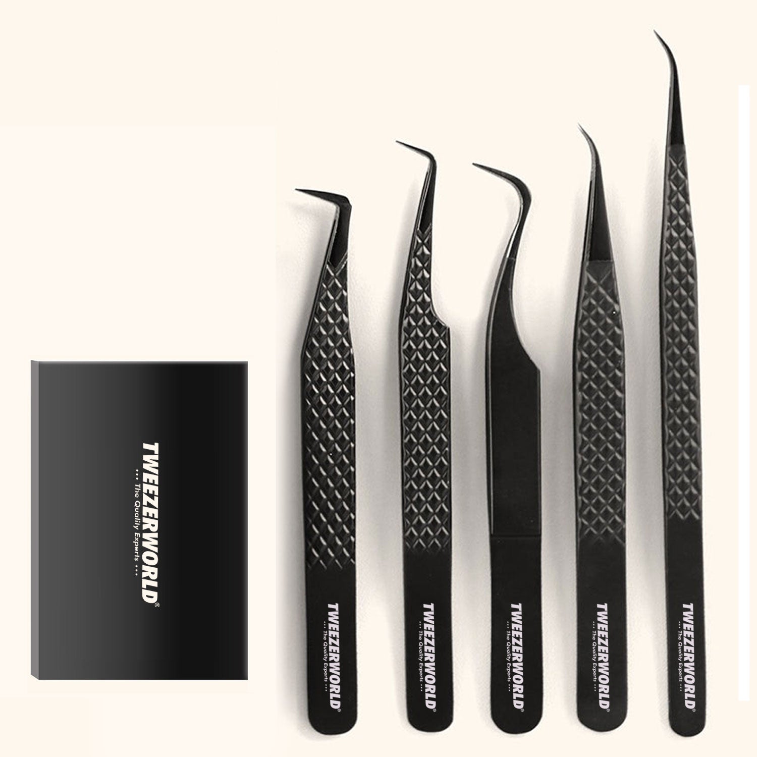
Explore TWEEZER WORLD®’s Professional Lash Tweezers and Fiber Tip Lash Tweezers.
What Does Tweezer Tip Alignment Mean?
Tip alignment describes the relationship between the two working ends when the tweezer is closed using a defined force. It is not a single yes-or-no characteristic. A complete inspection may consider:
- Lateral alignment: whether one tip sits to the left or right of the other when viewed from above.
- Vertical alignment: whether one tip sits higher than the other when viewed from the side.
- Tip crossover: whether the tips pass or slide across each other during closure.
- Twist: whether the arms or working ends rotate out of the intended plane.
- Contact location: where the inner faces first meet.
- Contact coverage: how much of the specified gripping area makes contact.
- Closed gap: any visible or measured separation at a defined point.
- Closure consistency: whether the same contact pattern appears when the tool is opened and closed repeatedly under comparable conditions.
The correct contact pattern depends on the model. A fine-point electronics tweezer, a wide boot lash tweezer, a slanted eyebrow tweezer and a soft-tip watch-service tool should not all be judged by one generic photograph or one universal gap limit.
Alignment Is Not the Same as Grip Performance
Alignment supports grip, but it does not prove every aspect of performance. Grip also depends on:
- Tip geometry and contact area
- Inner-tip texture or surface finish
- Spring tension and closing force
- Arm stiffness and return action
- Cleanliness and residue
- The size, shape and material of the object being handled
- User pressure, angle and technique
A fiber-tip texture cannot compensate for tips that meet outside the intended gripping zone. Equally, visually aligned smooth tips do not automatically guarantee that every lash diameter or component will be held without movement.
For that reason, a responsible quality system separates alignment inspection from functional grip testing. Both may be required, but the results should not be treated as interchangeable.
Why “Precision” Requires Careful Wording
In ordinary product marketing, “precision tweezers” often describes a general tool category. In measurement science, precision has a narrower meaning connected with the agreement of repeated results under stated conditions. The NIST guidance on precision terminology links precision with repeatability and reproducibility rather than using it as a synonym for general quality.
This distinction matters when a supplier publishes a numerical or absolute claim. Saying “0.05 mm maximum lateral offset, measured at the point shown on drawing TW-101 under the stated closing force” is a testable requirement. Saying “perfect precision” is not.
Advertising rules also generally expect objective product claims to have supporting evidence. The US Federal Trade Commission’s substantiation policy explains that objective claims should have a reasonable supporting basis. For UK marketing, CAP guidance on substantiation similarly distinguishes objective claims from obvious opinion or exaggeration.
Build a Defined Inspection Setup
An inspection result is more useful when another trained inspector can follow the same method and reach a comparable decision. Define the setup before inspecting production samples.
1. Identify the Exact Model and Intended Contact Area
Record the model number, batch or lot, tip pattern, material, finish and approved drawing revision. Mark the intended gripping zone on the drawing. Without a defined contact area, “the tips meet” can mean different things to different inspectors.
2. Clean and Condition the Tool
Inspect clean, dry tips. Adhesive, oil, polishing compound, coating residue or dust can create a false gap or hide an edge defect. If products are conditioned at a specified temperature or humidity before inspection, record those conditions.
3. Control Lighting and Background
Use consistent, diffuse lighting that makes the tip outline visible without strong glare. A contrasting matte background can help reveal offset and gaps. Reflective polished tips may require a different viewing angle from matte or coated tools.
4. Define the Magnification
Use a loupe, microscope or camera system appropriate to the tip size and acceptance limit. Record the selected magnification. Do not describe a visual check as microscopic inspection unless a microscope was actually used.
5. Standardize the Closing Force
Tip contact may change as pressure increases. A tool can appear misaligned under feather-light contact but settle into the intended gripping zone under normal working force. Excessive pressure can also force tips to cross or flex.
Define how the force is applied and where it is applied on the handle. For a repeatable production method, a fixture, force gauge or controlled displacement can be more consistent than an undefined hand squeeze. If the process uses manual closure, train inspectors against an approved reference and state that limitation.
6. Use an Approved Drawing and Golden Sample
A signed reference sample helps inspectors understand acceptable tip shape, contact progression, finish and tension. It should be linked to a controlled drawing and specification revision. A photograph alone may not show the same details from every viewing angle.
Step-by-Step Tip-Alignment Inspection
- Confirm identity. Match the product to the correct model, batch, drawing and inspection instruction.
- Check the open position. Look for unequal arm spacing, visible twist, permanent bending or an irregular return position.
- View from above. Close the tool using the specified force and check lateral offset, symmetry and crossover.
- View from the side. Check vertical step, tip height and whether one working end rises above the other.
- Inspect the front profile. Where practical, examine whether the two faces meet centrally rather than contacting at one corner.
- Observe first contact. Identify where the tips initially touch and whether that location matches the design.
- Check contact coverage. Confirm that the specified gripping zone meets without an unintended gap, rocking action or false contact behind the tip.
- Cycle the tweezer. Open and close it several times using comparable force to check whether the contact pattern remains consistent.
- Perform a separate functional test. Use a defined representative material, component or test medium suitable for the model.
- Record the result. Mark pass, fail or rework and retain the relevant measurement, photograph or inspection record.
Common Alignment Defects
| Observed condition | What it may indicate | Inspection response |
|---|---|---|
| One tip sits left or right of the other | Lateral offset, unequal forming or arm twist | Compare with the drawing limit and inspect from the side before deciding disposition. |
| One tip is visibly higher | Vertical step, uneven grinding or deformation | Inspect under defined magnification and check whether the intended contact zone is affected. |
| Tips cross during closure | Excessive force, arm imbalance, thin-tip flex or incorrect forming | Repeat under the specified closing force; reject or rework if crossover exceeds the approved criterion. |
| Contact occurs behind the working end | False grip or incorrect contact progression | Check the defined first-contact point and perform the model-specific functional test. |
| Only one corner touches | Face angle mismatch, twist or uneven finishing | Inspect the front profile and contact coverage. |
| Alignment changes between closures | Unstable arm movement, variable manual force or permanent deformation | Standardize the force and investigate repeatability before making a performance claim. |
| Visible gap disappears only under heavy force | Excessive spring tension, poor forming or an unsuitable acceptance method | Evaluate at the intended operating force rather than forcing a cosmetic pass. |
Separate Visual, Dimensional and Functional Checks
| Inspection type | What it can support | What it cannot prove alone |
|---|---|---|
| Visual alignment inspection | Tip relationship, crossover, obvious gap, symmetry and surface defects under stated viewing conditions | Exact numerical offset, long-term durability or performance with every possible object |
| Dimensional measurement | Defined gap, offset, width, thickness or contact location within the capability of the method | User comfort, grip security or the absence of all measurement uncertainty |
| Functional grip test | Performance with the stated test medium, force, angle and procedure | Universal performance across unrelated materials, techniques or applications |
| Closing-force test | Spring-force or tension result at the stated opening and measurement point | Tip alignment or grip quality by itself |
| Cycle or durability test | Retention of specified characteristics after the stated number of cycles and load conditions | Unlimited service life or resistance to misuse, drops and contamination |
When dimensional results are reported, the method should be suitable for the tolerance being evaluated. The NIST measurement-uncertainty guidance provides a useful foundation for understanding why a reported value should be considered together with the measurement process and its uncertainty.
Write Acceptance Criteria Before Inspection
“Good alignment” is too subjective for a purchase specification. Define the requirement in measurable or observable terms.
| Characteristic | Example specification structure |
|---|---|
| Contact location | First contact shall occur within the gripping zone identified on the approved drawing. |
| Lateral offset | Maximum permitted offset, measurement point, magnification and closing force to be stated. |
| Vertical step | Maximum permitted step at the defined point, using the agreed viewing or measurement method. |
| Tip crossover | No crossover at the specified closing force, unless the design intentionally requires another contact action. |
| Contact coverage | Minimum contact length, area or approved visual reference for the specified working zone. |
| Functional grip | Defined test medium, dimensions, orientation, force, duration and pass/fail outcome. |
| Closing force | Permitted force range measured at the stated opening and handle location. |
Example values should not be copied between unrelated models. Fine watch-service points, lash tweezer gripping faces and broader slant tips can require different limits and test methods.
100% Inspection vs Sample Inspection
A claim such as “every tweezer is inspected” should only be used if every unit receives the stated inspection. If the manufacturer checks a sample from each lot, the correct claim is “batch sampled” or “lot inspected according to the stated sampling plan.”
ISO 2859-1:2026 specifies acceptance-sampling plans for inspection by attributes. A sampling plan can help make a lot-acceptance decision, but it does not mean that every unit in an accepted lot is defect-free.
The control plan should identify:
- Characteristics checked on every unit
- Characteristics checked by lot sampling
- Inspection level and sample size
- Defect categories
- Acceptance and rejection numbers
- Reinspection and rework rules
- Records retained with the batch
Critical or commercially important alignment features may justify 100% inspection, but that decision should come from the product specification and risk assessment rather than from a marketing slogan.
Claims to Avoid—and Better Alternatives
| Overstated wording | Why it is risky | More supportable wording |
|---|---|---|
| Perfectly aligned tips | “Perfect” provides no tolerance, force or inspection method. | Tips inspected for alignment at the specified gripping zone. |
| 100% precise | It is undefined and implies an absolute result. | Manufactured to the approved tip geometry and inspection criteria. |
| Zero-gap closure | No measurement capability or contact location is stated. | Closed-tip gap checked at the defined point against the specified limit. |
| Never slips | Grip depends on the object, cleanliness, pressure and technique. | Grip tested with the stated representative material under the defined method. |
| Grips every lash | No one test necessarily covers every diameter, adhesive condition or technique. | Designed for the lash diameters and techniques listed in the product specification. |
| Scratch-proof tips | Contamination, trapped particles and excessive pressure can still mark a surface. | Non-marring or soft-contact tip option intended to reduce marking risk when clean and correctly used. |
| Hand-tested quality | The claim does not identify what was tested. | Each unit visually checked for tip contact and crossover under the documented inspection instruction. |
What an Alignment Inspection Record Should Contain
A short, controlled record is more useful than an untraceable close-up photograph. Include:
- Product name and model reference
- Batch or lot number
- Specification and drawing revision
- Date and inspector identification
- Lighting, magnification and background
- Closing-force or displacement method
- Measurement equipment and calibration status, where applicable
- Characteristics and limits inspected
- Sample size or confirmation of 100% inspection
- Results, defect classification and disposition
- Reference images, where they add useful evidence
Photographs should use a consistent orientation and include scale information when they are intended to support a dimensional conclusion. A phone image may document an obvious defect, but it should not be treated as a calibrated measurement unless the complete imaging method has been defined and validated for that purpose.
Model-Specific Inspection Priorities
| Tweezer type | Alignment priority | Additional functional check |
|---|---|---|
| Isolation lash tweezer | Fine-point meeting, no unintended crossover and clear sight line | Controlled separation and pickup using the stated lash diameter range |
| Volume or boot lash tweezer | Contact coverage across the approved sweet spot | Fan pickup test using a defined technique and lash material |
| Fiber-tip lash tweezer | Aligned textured faces without a false contact point | Grip test after confirming the inner surfaces are clean and residue-free |
| Eyebrow tweezer | Even slant or point contact without a sharp unintended corner | Representative hair-pickup test and edge-finish inspection |
| Electronics tweezer | Fine-point symmetry, stability and no crossover at the intended force | Component-handling test appropriate to the specified tip and ESD requirements |
| Watch-service tweezer | Fine contact, smooth edges and controlled closure | Task simulation with representative screws, wheels or scratch-sensitive parts |
| Replaceable or soft-tip tweezer | Tip seating, face symmetry and fastening security | Holding-force and marking-risk assessment using the intended component surface |
For another application-focused example, read the Precision Watch-Service Tweezers for Professional Workshops guide.
Procurement Questions to Ask a Tweezer Supplier
- Which exact alignment characteristics are inspected?
- Is the inspection performed on every unit or on a sample?
- What closing force or handle displacement is used?
- What magnification and lighting are specified?
- Where is the intended gripping zone shown?
- Are numerical limits included on a controlled drawing?
- What representative material is used for functional grip testing?
- How are failed units reworked, reinspected and recorded?
- Can the supplier provide a batch inspection summary?
- Will changes to tip geometry, forming, finishing or test methods require buyer approval?
Learn more about TWEEZER WORLD® manufacturing and OEM and private-label tweezer development.
Frequently Asked Questions
What does good tweezer tip alignment look like?
The two working ends should meet at the contact location defined for that model without unacceptable lateral offset, vertical step, twist or crossover. The exact acceptance limit should come from the approved drawing or reference sample.
Must the complete inner surface close with no visible gap?
No. Some tweezer designs use a defined sweet spot or progressive contact pattern. Inspect the intended gripping zone rather than assuming that every inner surface must close simultaneously.
How much magnification is required?
There is no universal magnification for every tweezer. Select a level that allows the specified characteristic and limit to be evaluated reliably, then record it in the inspection instruction.
Does a close-up photograph prove alignment?
A photograph can provide useful visual evidence, but the result depends on viewing angle, focus, lighting, scale and closing force. A photo alone does not establish a numerical measurement unless the imaging method is controlled for that purpose.
Does “hand tested” mean every unit is inspected?
Only if the documented process covers every unit. If testing is performed on a sample from the batch, describe it as batch or sample inspection and identify the sampling plan.
Can aligned tips still have poor grip?
Yes. Grip can be affected by surface finish, texture, contamination, spring tension, contact area, object dimensions and user technique. Alignment and functional grip should be tested separately.
Can a supplier claim “perfect precision” after a visual check?
That phrase is too broad to be supported by a basic visual check. It is better to state the exact feature inspected, the method, the limit and whether the inspection covered every unit or a defined sample.
Should every tweezer receive an alignment check?
That depends on the product specification, process controls, risk and commercial requirements. If every unit is not inspected, the supplier should not make an “every tweezer checked” claim.
Conclusion
Reliable tip-alignment inspection begins with a defined model, contact area, viewing method, closing force and acceptance criterion. Visual examination, dimensional measurement and functional grip testing answer different questions and should be recorded separately.
The strongest product claim is not the most absolute one. It is the claim that accurately matches the inspection evidence. Replace “perfectly aligned” with a specific statement explaining what was checked, how it was checked and which units were covered.
TWEEZER WORLD® can discuss model-specific tip geometry, approved samples, inspection criteria, private-label marking and batch documentation for professional tweezer programs.
Request a Tweezer Sample and Inspection Specification
Papular Products Gallery