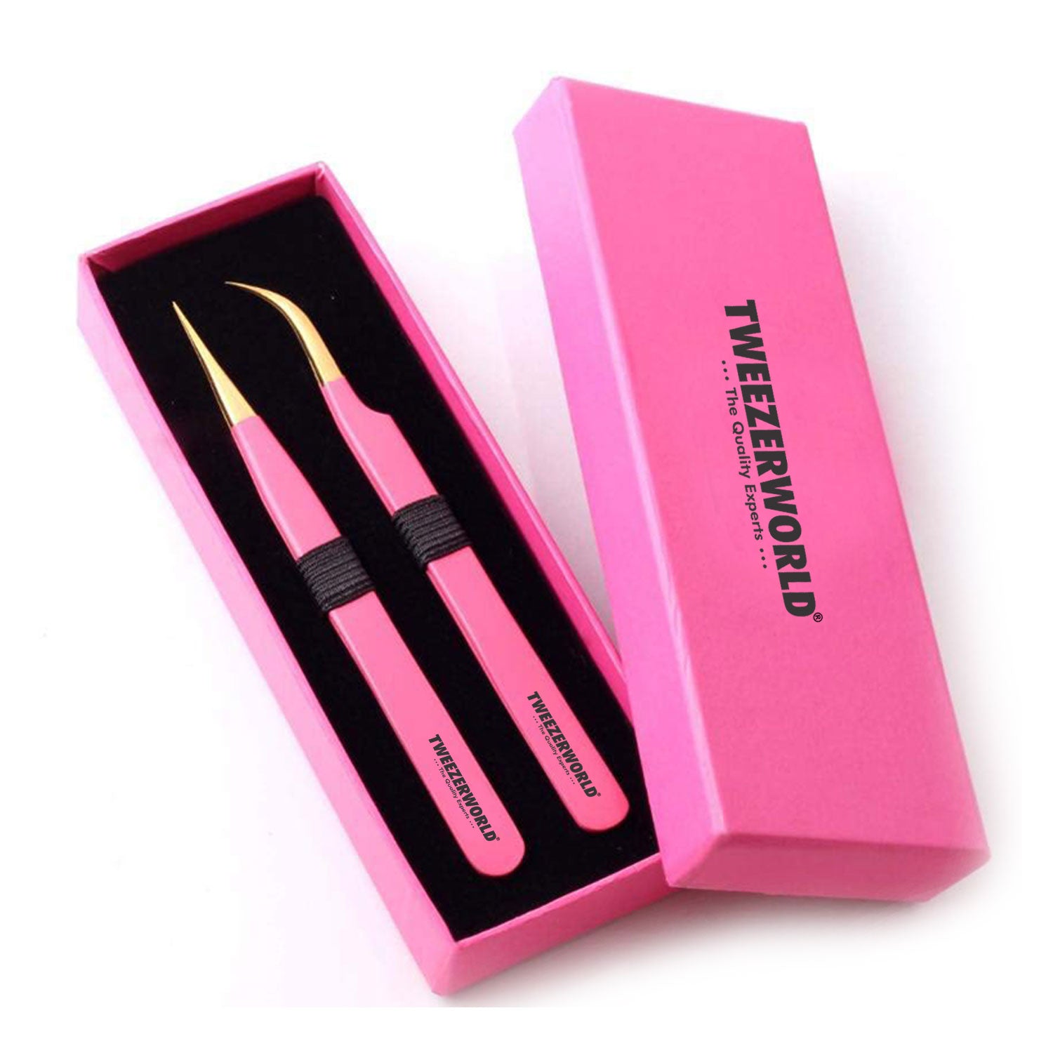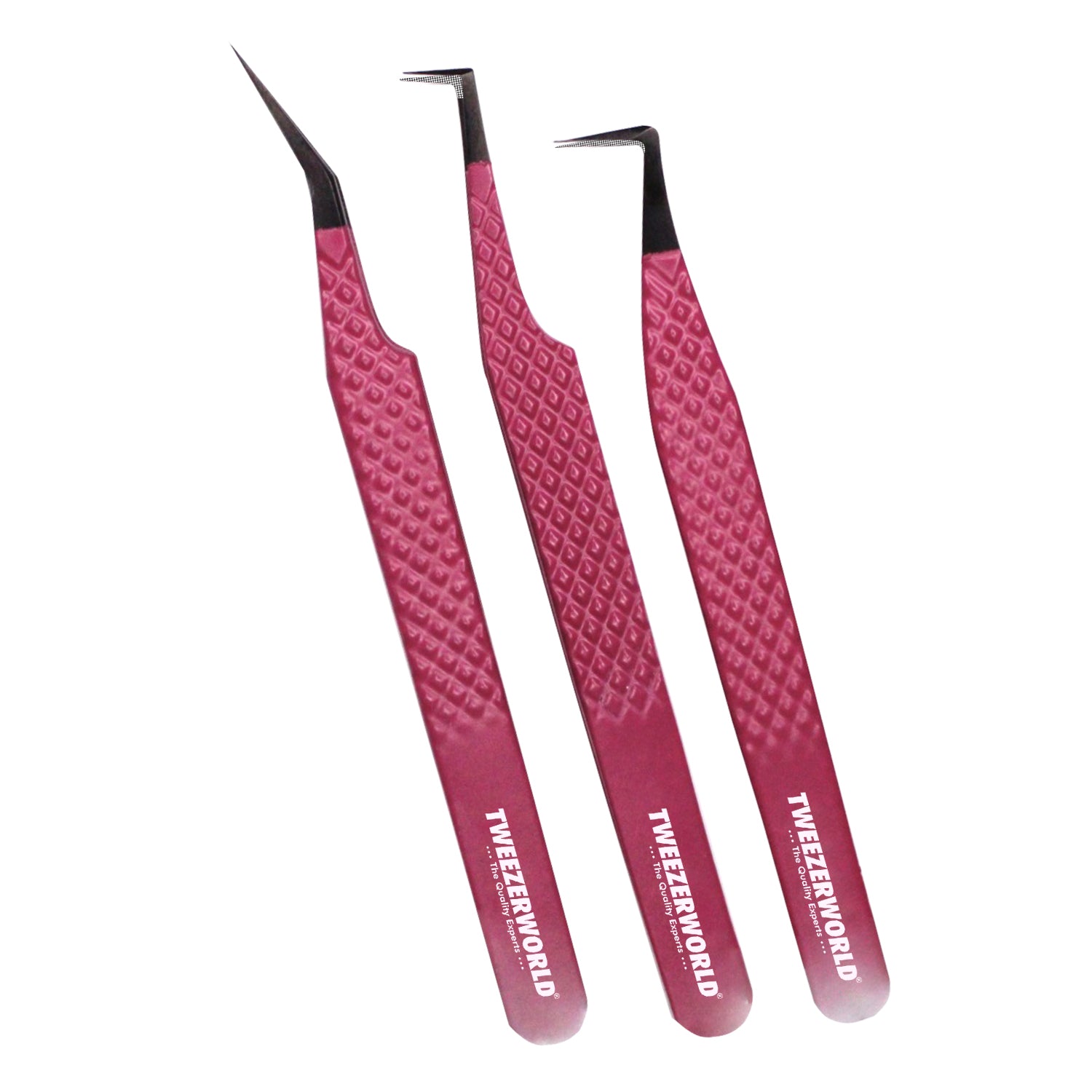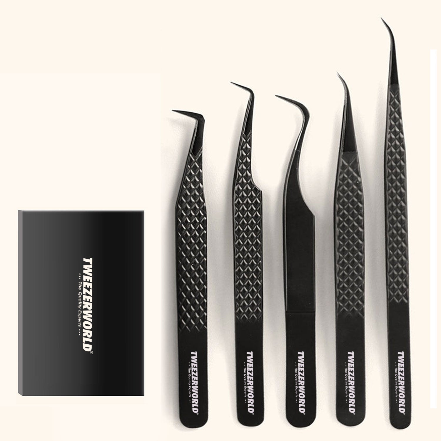

Optical Transceiver Tweezers for 800G & 1.6T
Optical Transceiver Tweezers: Tools for 800G and 1.6T Component Handling
Higher-speed optical transceivers place electronic, photonic, mechanical and thermal features into increasingly dense assemblies. That does not mean every 800G or 1.6T component requires the sharpest available tweezer. It means each handling operation needs a tool selected for the exact component, permitted contact zone, damage risk and process environment.
A fine conductive metal point may position a robust package accurately but scratch a coated optical surface. A polymer tip may reduce visible marking on a module housing but obstruct a narrow assembly area. A ceramic tip may suit a selected thermal or low-magnetic-interaction task but remain too hard for direct contact with a lens or polished fibre end face.
This guide explains how optical-module manufacturers, photonics laboratories, data-centre repair teams, distributors and OEM tool brands should select and specify tweezers for controlled 800G and emerging 1.6T component handling.
Quick answer: start with the component manufacturer’s approved handling zone and process instructions. Then choose the tip material, geometry, electrical behaviour, closing force, cleanliness and packaging required for that one operation. Approve the complete tweezer using representative components and measurable acceptance criteria. Never describe a tool as universally suitable for every 800G or 1.6T module.
Explore TWEEZER WORLD®’s ESD and Anti-Static Tweezers, ESD Stainless-Steel Tweezers, Ceramic Tweezers and Precision Tweezers.
This article is a tool-selection and procurement guide. It is not a transceiver-assembly work instruction, optical-cleaning procedure or electrical-safety guide. Follow the module, component, process-equipment and ESD-control documentation approved for the exact product.
Why 800G and 1.6T Need Task-Specific Tooling
“800G” and “1.6T” describe data-rate classes, not one universal mechanical construction. The IEEE P802.3df task force completed its 400 Gb/s and 800 Gb/s work with approval of IEEE Std 802.3df-2024. The active IEEE P802.3dj task force covers 200 Gb/s, 400 Gb/s, 800 Gb/s and 1.6 Tb/s Ethernet work. In parallel, the OSFP MSA describes an eight-lane pluggable form factor supporting 400G, 800G and 1.6T lane configurations, while the OIF’s current work includes 1600ZR and 1600ZR+ coherent-interface projects.
For procurement, the practical lesson is straightforward: do not qualify a tweezer against a data-rate label alone. Qualify it against a particular assembly, part and operation. Two modules sold at the same speed can use different housings, optical interfaces, internal layouts, thermal designs and manufacturing processes.
Separate Factory Assembly From Field Maintenance
The first specification decision is where the tool will be used.
| Environment | Typical permitted work | Tool-selection priority |
|---|---|---|
| Transceiver manufacturing | Handling approved packages, carriers, flex circuits, housings, clips and assembly aids | Process-specific geometry, contamination control, ESD compatibility and repeatable force |
| Photonics laboratory | Prototype assembly, inspection, positioning and controlled rework | Fine access, visibility, interchangeable tool roles and documented contact zones |
| Electronics rework centre | Board-level work performed under an approved rework procedure | ESD programme compatibility, heat tolerance where needed and tip durability |
| Data-centre field service | External module, cage, latch, label, cable-management or approved mechanical tasks | Cleanliness, controlled mechanical contact and protection of connectors and finished surfaces |
Field technicians should not open or internally rework a sealed optical transceiver unless the module manufacturer and service programme explicitly authorize that work. A tweezer set for external data-centre maintenance is not automatically suitable for internal optical-engine assembly.
Begin With the Permitted Contact Zone
Before selecting a tweezer shape, mark where the tool may touch the component. The component drawing, handling specification or controlled work instruction should distinguish permitted and prohibited contact areas.
| Component area | Primary risks | Preferred specification approach |
|---|---|---|
| Metal or ceramic package body | Slipping, indentation, residue and excessive force | Define tip width, contact length, closing force and approved grip faces. |
| Flex circuit or thin interconnect | Creasing, tearing, delamination and conductor damage | Use a smooth rounded or approved non-marring contact with a controlled low-force operation. |
| Lead, pad or connector feature | Bending, plating damage, contamination and lost coplanarity | Avoid gripping unless the approved process defines the location, geometry and force. |
| Lens, window or coated optical surface | Scratching, coating damage, particles and fingerprints | Do not contact with ordinary tweezers; use an approved edge, carrier or non-contact process. |
| Polished fibre end face | Scratches, chips and contamination that can affect optical performance | Never touch with tweezer tips. Follow the connector inspection and cleaning procedure. |
| Bare die, wire bonds or exposed photonic structure | Catastrophic mechanical or contamination damage | Use dedicated die-handling, vacuum or automated tooling validated by the process owner. |
| Housing, latch or thermal hardware | Cosmetic marking, deformation, slipping and contamination transfer | Choose a robust smooth, rounded or replaceable-tip tool matched to the mechanical load. |
If no approved contact zone exists, the correct next step is process clarification—not choosing a sharper tool.
Common Optical-Transceiver Handling Tasks
An optical module may contain or interact with several component families. The correct tool role depends on construction and assembly sequence, but procurement teams commonly need to evaluate tooling for:
- packaged laser, modulator, photodiode and driver components;
- photonic integrated circuit packages and carriers;
- ceramic submounts and miniature substrates;
- approved fibre ferrules, sleeves and mechanical alignment parts;
- flex circuits, small connectors and grounding features;
- springs, clips, retainers, shields and fasteners;
- thermal pads, films, spacers and heat-spreader hardware;
- module housings, pull tabs, latches and exterior labels;
- protective caps and dust plugs; and
- inspection samples, process coupons and assembly fixtures.
These are potential handling categories, not permission to grip every listed part. The approved drawing and work instruction remain authoritative.
Tool Selection by Tip Material
| Tip material | Potential advantages | Important limitations | Possible transceiver tasks |
|---|---|---|---|
| Stainless steel | Rigid, durable, cleanable and available in very fine geometries | Can scratch soft finishes, concentrate force and behave as an ungrounded conductor if not controlled | Robust package bodies, clips, fasteners and defined precision-assembly operations |
| Low-magnetic-response or anti-magnetic alloy | Reduced magnetic interaction for selected miniature metal parts | The exact alloy, hardness, magnetic response and corrosion performance still require specification | Operations where retained magnetism or magnetic attraction is an identified process risk |
| Titanium alloy | Low mass, corrosion resistance and generally lower magnetic interaction than common steels | Not automatically non-marring, non-magnetic, ESD-safe or suitable for every cleaning chemistry | Fatigue-sensitive precision work and selected low-magnetic-interaction processes |
| Ceramic | Electrical insulation at the contact tip, heat resistance and low magnetic interaction | Hard and potentially brittle; can chip and can damage glass or coatings; the complete tool is not a live-voltage safety tool | Selected hot, solder-adjacent or electrically isolated contact operations validated by the process owner |
| Engineering polymer | Broader, gentler contact and reduced risk of visible metal marking | Wear, particles, chemical compatibility, static behaviour and temperature limits must be verified | Approved housings, flex circuits, labels, films and scratch-sensitive mechanical surfaces |
| Carbon-fibre-composite tip | Replaceable geometry and potentially dissipative formulations | Electrical resistance varies by formulation; wear debris, cleanliness and solvent compatibility require testing | Defined ESD-controlled handling of approved packages and mechanical surfaces |
Material names alone are not acceptance criteria. Buyers should request the exact material or permitted family, relevant electrical properties, temperature range, chemical compatibility, wear expectations and batch documentation.
For a deeper material and geometry comparison, read Photonics Component Tweezers: How to Select Contact Material and Tip Geometry.
Tool Selection by Tip Geometry
| Geometry | Best suited to | Procurement warning |
|---|---|---|
| Fine straight point | Direct access to small robust packages and lightweight electronic parts | Very fine points bend more easily and create high local pressure. |
| Fine curved point | Recessed areas and improved visibility around shields or housings | Define the curve, approach angle and closed-tip alignment. |
| Flat or paddle tip | Films, thermal interface pieces and components needing distributed contact | A broad tip can still crease or contaminate a thin material. |
| Rounded or blunt tip | Robust mechanical features and selected flex or cable-management tasks | Rounded metal is not automatically non-marring. |
| Angled or bent tip | Side access, horizontal placement and work under visual obstruction | Specify the working angle and contact-face orientation. |
| Reverse action | Hands-free holding of approved parts in a fixture or inspection process | Continuous spring force can deform fragile parts; measure the holding force. |
| Replaceable non-marring tips | Approved finished housings, films and other scratch-sensitive mechanical contact zones | Define tip retention, wear limit, replacement interval and cleanliness. |
ESD Control: Specify a Measured Property
Lasers, drivers, photodiodes, DSPs and supporting electronic assemblies can be electrostatic-discharge sensitive. The current IEC 61340-5-1:2024 provides requirements for an ESD-control programme. A tweezer must therefore be selected as one technical item within the complete programme, together with personnel grounding, work surfaces, packaging, process controls and verification.
A black coating, plastic handle or product name containing “ESD” does not prove electrical performance. The purchase specification should state:
- whether the tool should be conductive, dissipative or insulating at the contact area;
- the required resistance range and test method, where applicable;
- measurement points and environmental conditions;
- whether the requirement applies to the tip, handle or complete tool;
- grounding or operator-use conditions;
- verification frequency and record retention; and
- cleaning and wear conditions that may change resistance.
Do not confuse ESD-program compatibility with voltage insulation. Ordinary ESD, stainless-steel, titanium and ceramic-tip tweezers are not automatically rated for live electrical work.
Cleanliness Matters as Much as Geometry
A correctly shaped tip can still transfer oil, polishing compound, fibres, adhesive or abrasive particles. In optical assembly, contamination can be more damaging than a visible handling mark.
The buyer should define:
- the required supply cleanliness;
- permitted cleaning agents and rinse quality;
- particle and residue limits where controlled;
- cleanroom packaging requirements;
- individual tip protection;
- storage between operations;
- segregation of tools used with adhesives, thermal compounds or general hardware; and
- inspection and replacement criteria.
Tweezers should never be used to clean a polished optical end face. Follow the approved inspection and connector-cleaning system instead.
Closing Force, Contact and Release
Tip alignment is necessary, but it does not prove that the tool controls the component correctly. The specification should define the complete grip-and-release behaviour.
Initial Contact
Identify where the jaws should first meet. Fine pointed tweezers may require tip-first contact, while flat or broad models may require a defined parallel contact length.
Closing Force
Measure the force at a stated opening and handle position. “Soft tension” and “firm tension” are useful categories only when tied to a range or approved reference sample.
Lateral Stability
The part should remain within the approved contact zone during the defined movement. Check for jaw crossing, twisting and side slip.
Release
The component should leave the tips without sticking, springing, rotating or being drawn into an adjacent structure. A tool that picks up reliably but releases unpredictably has not passed the complete operation.
Recommended Optical-Transceiver Tweezer Set
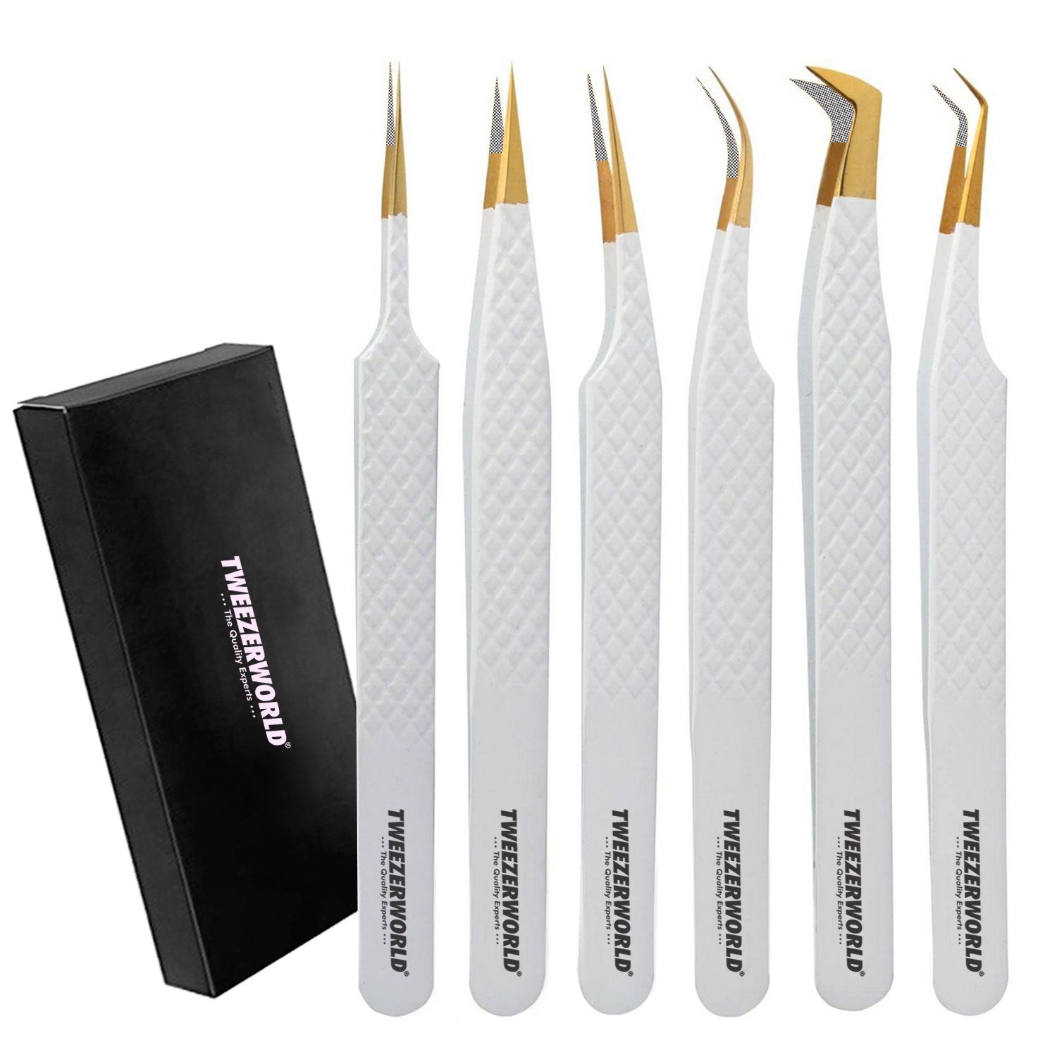
A distributor set should contain distinct tool roles rather than several visually similar points. A six-piece starting configuration may include:
- Fine straight ESD-program-compatible tweezer for defined small-package and electronic-component tasks
- Fine curved ESD-program-compatible tweezer for recessed access and improved visibility
- Medium rounded stainless-steel tweezer for robust clips, retainers and mechanical hardware
- Replaceable polymer or composite-tip tweezer for approved scratch-sensitive mechanical surfaces and flex materials
- Ceramic-tip tweezer for selected heat-adjacent or electrically isolated tip-contact processes
- Reverse-action tweezer for controlled holding in fixtures, inspection or assembly
Add long-reach, paddle-tip or specialty ferrule-handling tools only when the actual work instruction justifies them. Remove any model that duplicates another tool without a measurable process advantage.
For related technician kits, read Data-Centre Electronics Tweezer Set: Tools for Maintenance and Repair.
Acceptance Tests for Sample Approval
| Characteristic | What to define | Example evidence |
|---|---|---|
| Model identity | Part number, material, geometry, finish and revision | Controlled drawing and sample label |
| Dimensions | Overall length, tip width, thickness, angle and contact length | Dimensional inspection report |
| Alignment | Tip offset, crossing, closure sequence and permitted gap | Magnified inspection under defined closing force |
| Closing or holding force | Measurement location, opening and acceptable range | Force-gauge results |
| Electrical behaviour | Required resistance characteristic and applicable method | Model- or batch-specific test record |
| Surface condition | No burrs, pits, loose coating, sharp unintended edges or residue | Visual and magnified inspection |
| Cleanliness | Permitted particles, residues and packaging condition | Approved cleaning and inspection record |
| Functional handling | Representative part, contact zone, motion, hold and release criteria | Controlled qualification trial |
| Replaceable-tip security | Fastener torque, retention, alignment and replacement method | Assembly and pull/retention check |
| Durability | Repeated cycles, cleaning exposure and wear limit | Lifecycle or simulated-use report |
Completed Distributor Procurement Checklist
| Procurement field | Buyer’s requirement |
|---|---|
| Application | 800G/1.6T optical-transceiver manufacturing, laboratory assembly, rework or field maintenance—state one |
| Target components | List exact packages, housings, flex parts, clips, thermal materials or fixtures |
| Permitted contact zone | Reference controlled drawing, image or work instruction |
| Prohibited contact zone | Optical aperture, polished end face, wire bonds, bare die, coating or other protected area |
| Tweezer pattern | Straight, curved, rounded, paddle, reverse action or replaceable tip |
| Tip material | Declared metal, ceramic, polymer or composite formulation |
| Dimensions | Overall length and working-end dimensions with measurement locations and tolerances |
| Alignment | Contact sequence, maximum offset, crossing prohibition and closed-tip gap |
| Force | Closing or holding-force range at a defined opening and measurement point |
| Electrical requirement | Conductive, dissipative or insulating characteristic with test method and limits |
| Temperature | Operating exposure and permitted dimensional or functional change |
| Chemical compatibility | Approved cleaners, solvents and process chemicals |
| Cleanliness | Supply-cleaning, particle, residue and packaging requirements |
| Functional test | Representative component, grip location, motion, duration and release criteria |
| Marking | Brand, model, lot or colour identification without contaminating the working end |
| Packaging | Individual protection, ESD-protective packaging where required, case and labels |
| Documentation | Drawing, material declaration, inspection report and applicable test records |
| Golden sample | Signed sample linked to drawing and specification revisions |
| Production inspection | Critical, major and minor characteristics with sampling or 100% checks |
| Change control | No unapproved material, geometry, process, coating, supplier or site change |
Avoid Unsupported Product Claims
Terms such as “800G compatible,” “1.6T certified,” “cleanroom safe,” “non-scratch,” “ESD safe” and “zero contamination” can imply more than a general-purpose tool specification proves.
| Weak claim | Why it is incomplete | Better wording |
|---|---|---|
| “Universal 800G/1.6T tweezer” | Modules and internal parts use different constructions and handling rules. | “Precision tweezer configurable for defined optical-transceiver assembly tasks.” |
| “ESD safe” | No resistance value, method, component or ESD programme is identified. | “Available with specified electrical characteristics for evaluation within the buyer’s ESD-control programme.” |
| “Non-scratch tips” | Any contaminated, worn or overloaded tip may mark a surface. | “Replaceable polymer tips intended to reduce metal contact on approved surfaces; sample validation required.” |
| “Safe for optical lenses” | Direct lens or coating contact may be prohibited. | “Use only on the component manufacturer’s approved handling zone.” |
| “1.6T certified” | A data-rate label is not a tweezer certification scheme. | “Manufactured and inspected to the agreed model-specific procurement specification.” |
OEM and Private-Label Options
TWEEZER WORLD® can develop distributor and workshop sets with:
- fine straight, curved, angled, rounded and reverse-action patterns;
- stainless-steel, titanium, ceramic and replaceable-tip constructions;
- model-specific alignment and spring-tension requirements;
- laser-marked model and brand identification;
- colour coding by tool role;
- individual tip protection;
- ESD-compatible cases and packaging where specified;
- custom foam layouts and technician-set cases;
- inspection reports and golden samples; and
- wholesale and private-label packaging.
Learn more about OEM ESD Tweezer Manufacturing, OEM and Private-Label Manufacturing and TWEEZER WORLD®’s Wholesale Programme.
Frequently Asked Questions
Can one tweezer be used for every 800G and 1.6T transceiver?
No. Data rate does not define the module’s complete mechanical construction or handling requirements. Select the tool for the exact component, contact zone and process.
Are ESD tweezers electrically insulated?
Not necessarily. Conductive or dissipative ESD tools and insulating ceramic tips serve different purposes. None should be treated as a live-voltage safety tool unless it carries an applicable rating and is used under an approved procedure.
Can tweezers touch an optical connector end face?
No. Do not touch polished fibre end faces with tweezer tips. Use the inspection and cleaning method approved for the connector.
Are ceramic tips safe for lenses?
Not automatically. Ceramic is hard and may damage glass edges or coatings. Direct optical-surface contact should be avoided unless a validated component-specific process explicitly permits it.
What does non-marring mean for a tweezer?
It should describe a verified reduction in marking risk on a defined surface under stated conditions—not an absolute guarantee. Tip cleanliness, wear, force and trapped particles still matter.
Which tweezer is best for flex circuits?
A smooth rounded, paddle or approved polymer/composite tip may distribute force better than a sharp point. The correct choice depends on the flex construction, permitted grip zone and required movement.
Should distributors request electrical test data?
Yes, when the product is sold with a conductive, dissipative, insulating or ESD-related claim. The report should identify the exact model, test method, measurement points and conditions.
What should be inspected on every precision tweezer?
Model identity, working-end condition, burrs, alignment and obvious contamination are common checks. The risk assessment should determine whether other characteristics require 100% inspection or sampling.
When should a tweezer model be requalified?
Requalify when changes to material, tip geometry, tension, coating, replaceable-tip formulation, production process, site or intended component could affect performance.
What should an optical-transceiver tweezer set contain?
A practical starting set includes fine straight and curved ESD-program-compatible tools, a robust rounded metal tool, a replaceable non-marring tip, a ceramic-tip model and a reverse-action holder. Final contents should follow real process tasks.
Conclusion
800G and 1.6T optical-transceiver work does not require one universally “advanced” tweezer. It requires a controlled selection of tools matched to specific packages, mechanical parts, flex materials, thermal features and assembly operations.
Begin with the permitted contact zone. Then define tip material, geometry, electrical behaviour, cleanliness, force, release performance and packaging. Approve the complete model with representative parts, retain the test evidence and control production changes.
That approach gives manufacturers a repeatable handling process, gives distributors a measurable procurement specification and prevents broad compatibility claims from replacing real product qualification.
Build an Optical-Transceiver Tweezer Set
Send TWEEZER WORLD® your component list, permitted contact zones, ESD requirements, preferred tool patterns, packaging and inspection criteria.
Choose an AI Optical Handling Category
Specify your task as Optical Component Handling; VCSEL/PIC Evaluation Tools; Transceiver Assembly & Inspection Tools; Fine Electronics/Connector Handling; or ESD-Controlled Models supported by model-specific testing. Submit the component drawing, permitted contact zones, required closing force and acceptance criteria for sample evaluation.
Compare the five handling categories and required evidence. ESD suitability requires documented results for the exact configuration. Ceramic or coated tips alone do not qualify a model.
Papular Products Gallery